
Sensing
Dimensional Sense
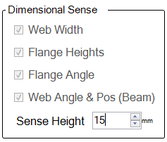
This section allows control over which measurements will be taken by the XB1200 when a new piece of material is loaded.
Note: Most of these settings are now automated and the user cannot change the option
Sense Height allows you to specify how high the torch will be positioned above the material when measuring the dimensions of a new length. Too low will cause the torch to crash into material that is over sized when compared to the profile library. Too high will add excessive time to the sensing routine. 10mm to 15mm is usually a good setting.
Cut Zone Sense
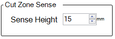
This setting applies to the sensing of each zone before cutting. It controls the starting height of the torch before commencing the sensing move.
Too low will cause the torch to crash if the material has any deflection or variation over the unsupported length. To high will add extra time to each job. 15mm is usually a suitable setting
Pre-Cut Sense
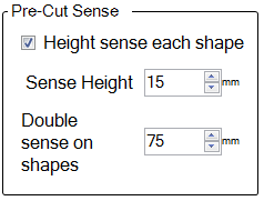
This section controls the sensing behaviour at the start of each cut.
Height sense each shape forces the machine to re-sense the surface before every shape
Sense Height is the position above the material that the sensing begins from.
Double sense on shapes is a threshold setting. Shapes bigger than this size (in any dimension) will get a second sense at the furthest location from the start point. This avoids crashing the torch if there is a twist in the material.
Reference Edges
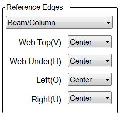
When the material is out of tolerance (with reference to the standard profile dimensions) the XB1200 will automatically modify the drawing to suit.
These settings allow the machine to compensate differently for each type of profile. It is common for everything to be aligned to the centre on RHS, UB or UC. However, on Angle it is often desirable for all cuts to be referenced to the heel of the angle. On Channel such as PFC it is common to centre the cuts on the web but reference the cuts on the flanges to the heel.
The available options are:
- By file – This uses a parameter in the file to control this setting
- Bottom – Moves the shapes with reference to the bottom as shown in the drawing – not related to the orientation of the material on the machine
- Centre – Keeps all cuts referenced to the centre of the face
- Top – Moves the shapes with reference to the top as shown in the drawing – not related to the orientation of the material on the machine
Some examples:
The flange width is defined as 124mm by the profile library.
The machine measures the flange of the actual steel as 128mm
The particular face is referenced to the TOP
A hole that is drawn central on the face (62mm from top and bottom) will remain 62mm from the top edge as drawn in the file
The outside cuts will also maintain their position with reference to the top edge of the face (as drawn in the file). The external cuts will be automatically extended to the bottom edge of that face
Another face is referenced to the CENTRE
A hole that is drawn central on the face (62mm from top and bottom) will remain central to the face and will now be 64mm in from either edge
The outside cuts will also maintain their position with reference to the centre of the face. The external cuts will be automatically extended to either edge of that face